To complete the disassembly you will need a Phillips ph0 screwdriver (and thermal compound if removing the mainboard).
Note: The screws for each component are slightly different lengths. We would advise keeping each set separate (and label) if possible.
To begin, place the StarBook Mk V or VI on a soft protected surface to avoid any possible scratching of the anodized finish.

1. Remove the 2x long Phillips screws from the backplate, these are located in the top corners.

2. Remove the remaining 8x short Phillips screws from the backplate.

3. Carefully remove the backplate.


4. Remove Battery: Remove 5 x phillips screws that hold the Battery in place.
Note: The centre right screw is intentionally absent.

Disconnect the battery connector.


5. Remove the SSD: Remove the screw holding it in place and slide it out.

6. Remove Memory: Press the silver clips on either side down and outwards to release the memory, then slide it out.

Repeat on the other side

6. Remove Wireless Card: Lift the plastic cover to access the antenna, and carefully lift them off.


Finally remove the screw holding the wireless card in place and slide it out.

7. Remove I/O Board: Lift the ribbon cable clamp to detach the ribbon cable.

Remove the 2x Phillips screws that hold the I/O Board in place. You can then lift it out.

8. Disconnect the screen: Lift the screen connector clamp to detatch the screen connector.

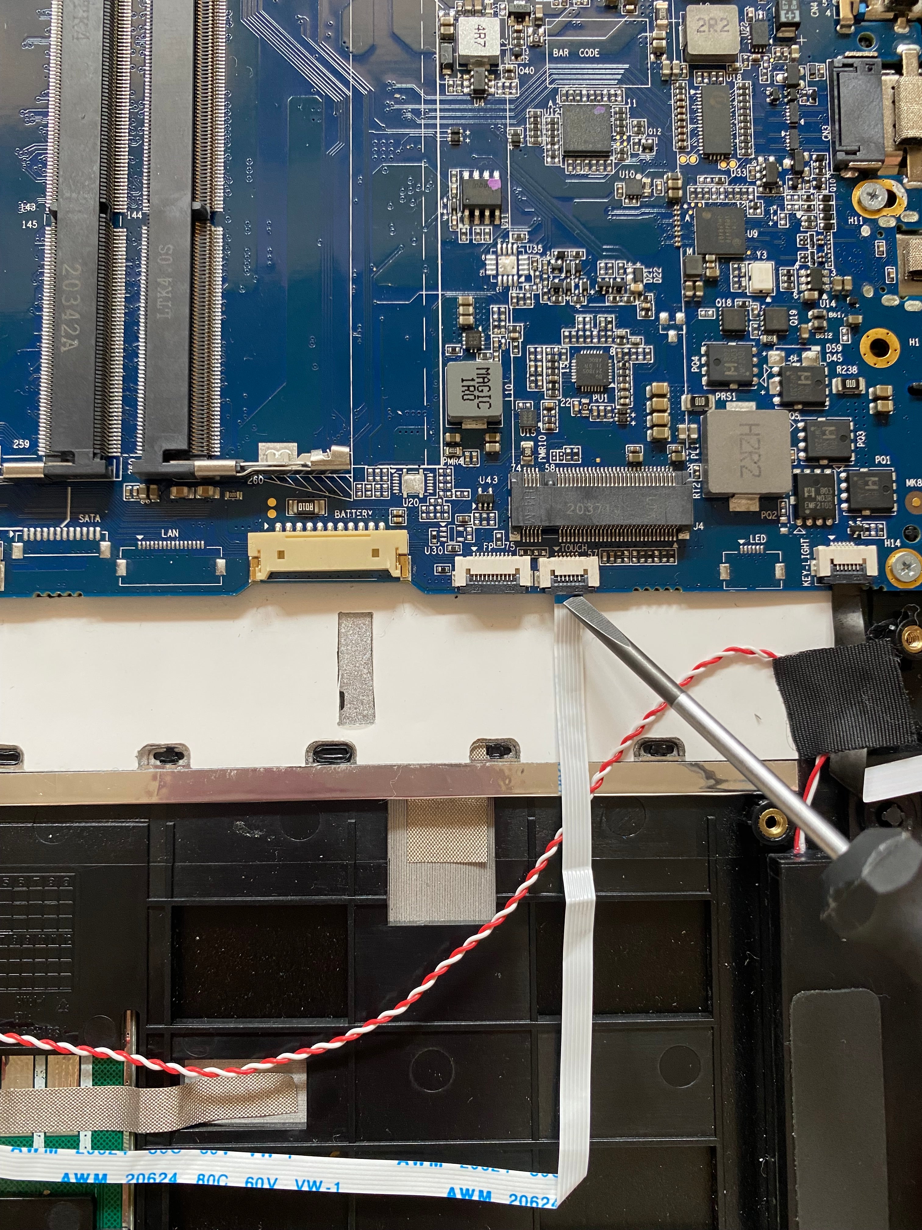
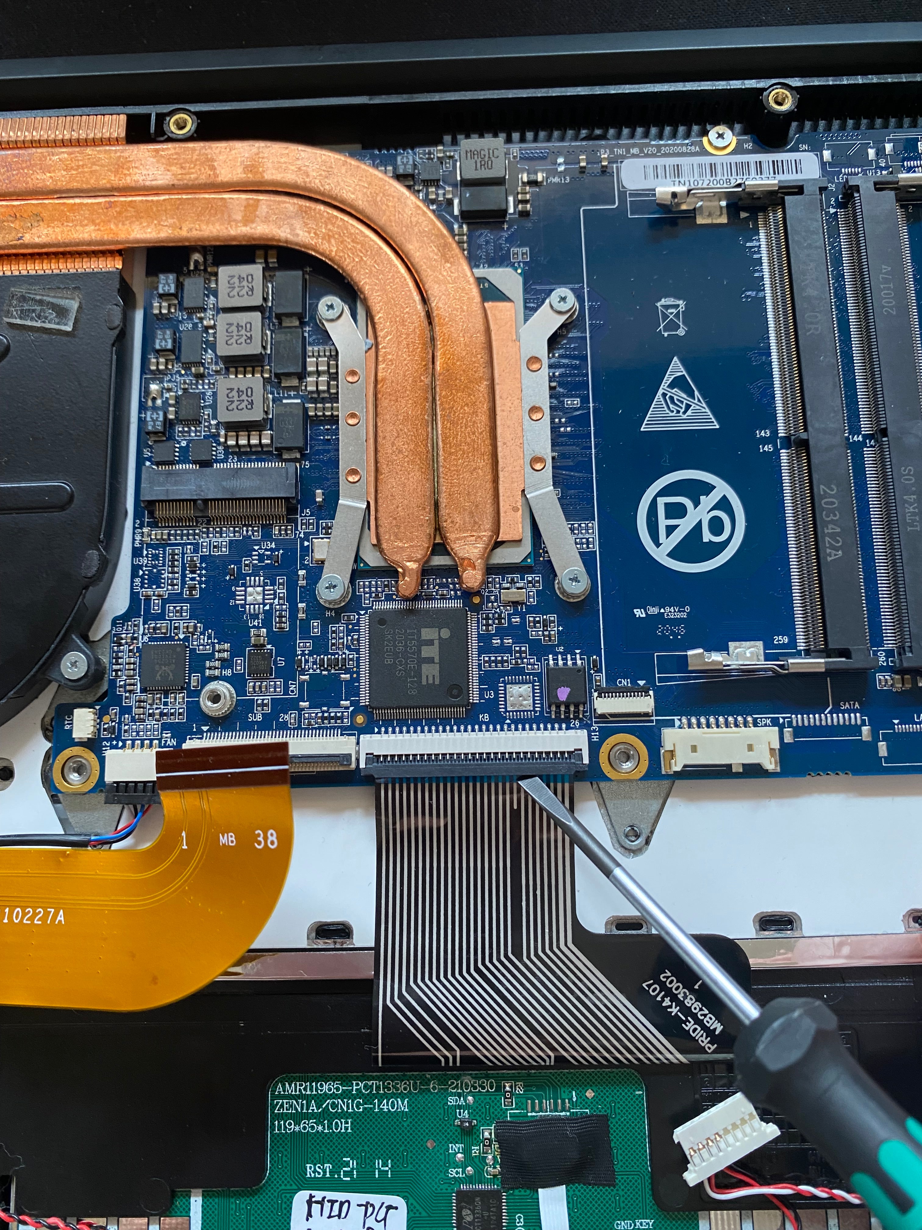
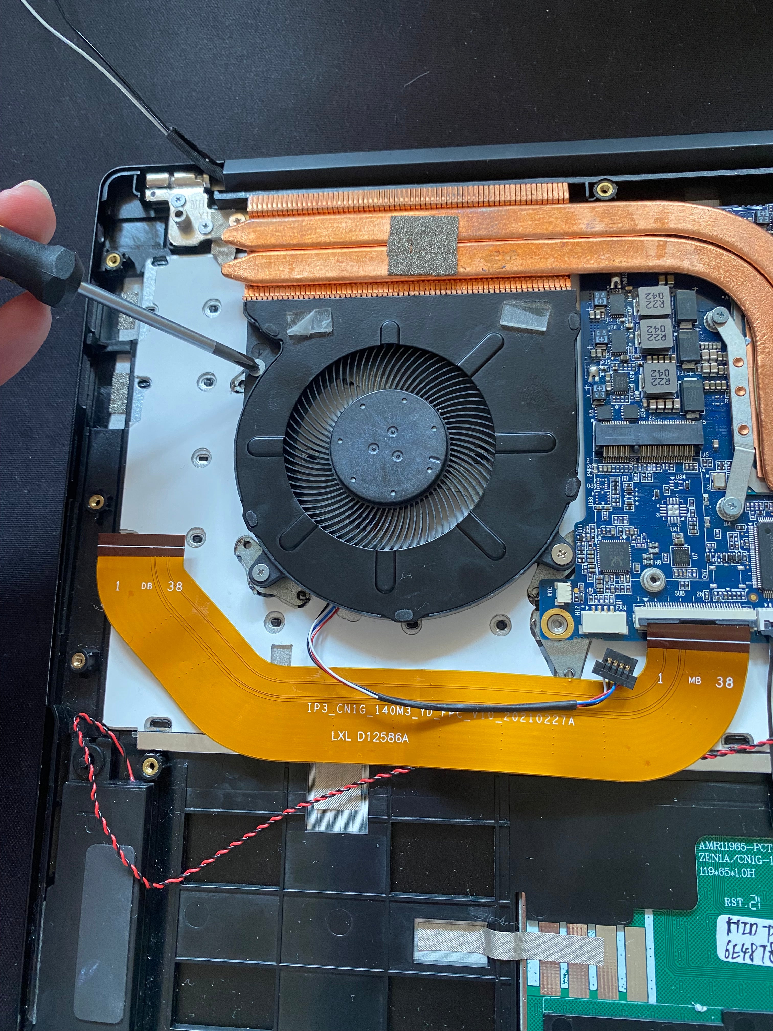
9. Disconnect the following ribbon cables/connectors from the Mainboard: I/O Board, Keyboard, Speakers, Trackpad, Finger Print Reader (Mk VI only)
I/O Board:

Touchpad:

Speakers:

Keyboard & keyboard back light:


10. Remove the DC Jack: Remove the 2 silver Phillips screws connecting the DC Jack shield to the mainboard. You can then disconnect the cable from the mainboard afterwards.

11. Remove the fan: Disconnect the fan from the mainboard

Remove 3 x Phillips screws from around the CPU fan and lift it off.


12. Remove the heat sink: Remove 4 x short Phillips screws, and lift the heat sink off the mainboard.
(Note: These screws are shorter than the rest of the silver philips screws)


13. Remove the Mainboard: Remove the remaining 4 x Phillips screws from around the edge of the mainboard and lift away from the chassis.


14. Remove the I/O ribbon cable from the chassis.

15. Removal of the Display Array:
15.1 Remove the 4x Phillips screws from the left hinge....

15.2 And then the right hinge.

15.3 Carefully lift the hinges on both sides to 90 degrees, to allow the chassis to clear the hinges.


15.4 Then lift the chassis to slide away from the display array.

16. Disassembly is now complete.

17. Reassembly is the reverse of these steps.
Please note- When re-attaching the heat sink to Mainboard, thermal compound should be used.
Start by cleaning the old compound off both the heat sink and processor with a cloth.


Reapply a small amount of compound to the processor, before carefully placing heat sink back on top.

